Gotta Keep ’em Separated
As the proliferation of devices that connect to your home network continues to grow. We need a better set of controls of what these devices can do once on your network. Especially taking into consideration the recent RansomeWare and BotNet like take overs that can really break your heart if it happens to wipe your prized devices which contain all your important things. (Of course you have a back up, I know we all do).
Upgrade The Network
Consumer grade Netgear and Linksys device Routers and some other WiFi Access Points combos are not entirely feature rich for this type of effort. Of course some of them if manipulated properly with aftermarket firmware could support what we’re about to plan and test. I found it just isn’t worth the headache.
For this process which is first going to be done in a sandbox so that it doesn’t impact what we’ll call our “Production” environment.
(For the record, this is just so that we don’t mess anything up and impact Netflix or Plex binge watching of shows and movies which are all working right now…)
- Router – Both Software and Hardware
- OPN Sense running on a lower power computer platform with dual NIC adapters on board. SSD + RAM installed
- Network Switch – PoE for Cameras and Sensors running on RasPi
- Installing a Managed Switch to control the Network Layers allowing for a VLAN Segmentation of the network
- This is how the Network will get divided into parts so that some devices cannot/should not see other devices.
Some terminology explanation is that VLAN means “Virtual Local Area Network or Virtual LAN which allows the devices to be isolated on a VLAN. The network packets are tagged by either HOST Computer or the Network Switch so that the connectivity only connects those devices on the same tagged VLAN environment.
“What’s In The Box???”
The largest need for this segmentation of the network is to place the devices that might have the least security into a separate area where they can only see each other and not anything else more critical on the network.
(I’m looking at you IoT devices)
So with that we start to place all the devices into VLANs which would make them in their own little Virtual Sandbox either to be protected or to stop some devices from getting too crazy.
- VLAN 10 (Home, Production, expected & trusted things)
- Home computers, laptops, phones
- Network Attached Storage, Hyper-V Server
- WiFi Network Controller (UniFi, Ubiquiti Cloud Key)
- RasPi PiHole and VPN Server
- VLAN 20 Network Monitoring / IDS Test Devices
- Not exactly a perfect location for these devices as they require some Network Switch manipulation like Port Mirror or Port Spanning
- FING Box and AKITA Box sitting on this VLAN
- Gravwell (Future testing needed, VM on Hyper-V Server
- Dedicated NIC Port on Hyper-V Server
- Grafana (Still working out configuration)
- Dedicated NIC Port on Hyper-V Server
- Security Onion (Network Monitoring, VM on Hyper-V)
- Dedicated NIC Port on Hyper-V Server
- PRTG (another network monitoring VM on Hyper-V)
- Dedicated NIC Port on Hyper-V Server
- VLAN 30 – All The Non-Trusted Things
- Guest LAN and WiFi Network
- PC/Laptops that are possibly compromised
- ACL List Denies all local connections, limited Port Connections outbound
- VLAN 40 – All Your IoT Are Belong To This :)
- Smart Oil Monitor
- Multiple RasPi Temp/Humidity Senors
- Rachio Sprinkler Controller
- Blossom Sprinkler Controller
- PoE Network Security Cameras
- Network Video Recorder for Cameras
- Synology Network Attached Storage (logs, Security Cam files)
- EcoBee Thermostats
- Smart TV
- WiFi / LAN connected printer
But what about the WiFi Things?
Don’t worry – they’re getting their own box – its just separated at the WiFi Controller and tagged for VLAN control as the devices connect to the different SSID’s in the house.
- SSID 01 – VLAN 10
- SSID 02 – VLAN 20
- SSID 03 – VLAN 30
- SSID 04 -VLAN 40
- SSID 05 – VLAN 40
Some of the IoT devices require a Legacy Mode on the WiFi AP so I’ve been giving the Legacy Mode its own SSID so that it doesn’t impact the speed of other non-Legacy requiring devices. So that helps explain the SSID04 and 05 being on the same VLAN.
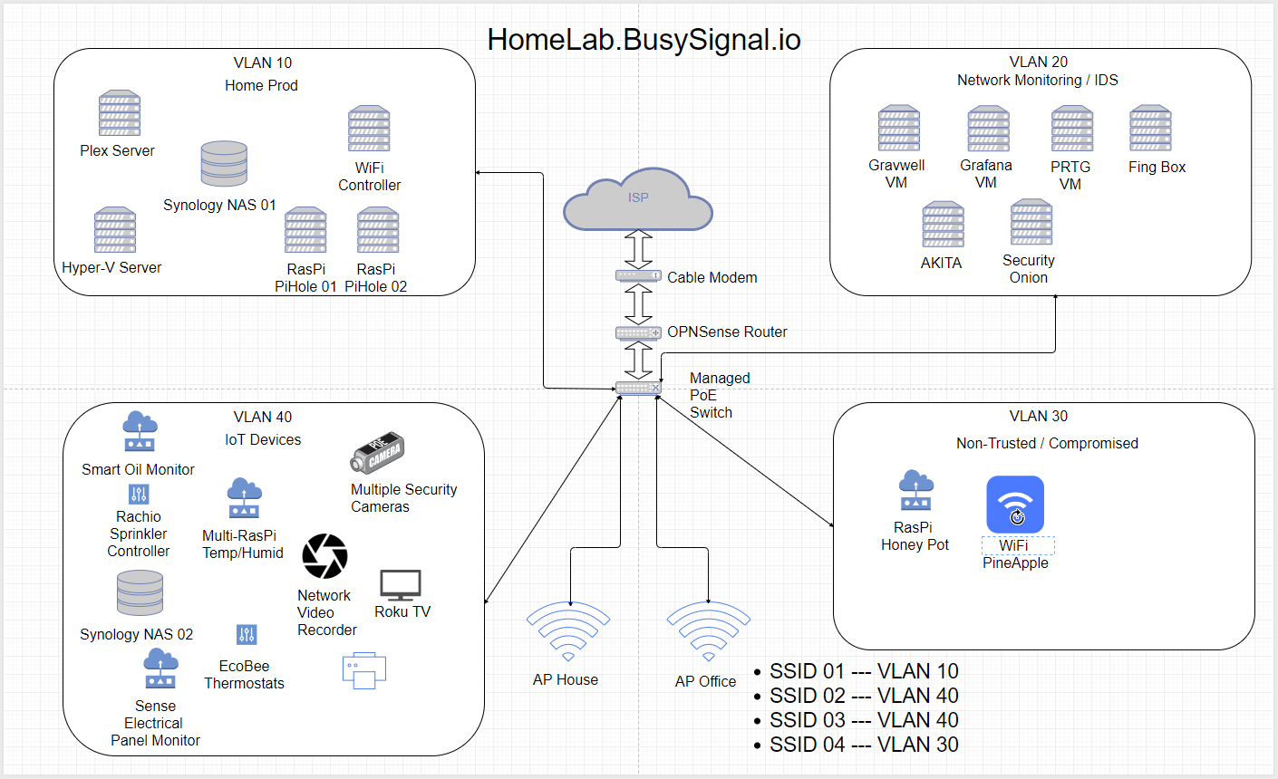
Diagrams Or Didn’t Happen
Working through some of the logistics, adding RAM to the VM Server and then adding a 4 port NIC to dedicate some VLANs right on the NIC to the Switch – I finally got the Network Diagram together.
VLANs and Port Controls
The VLANs are just part of the scenario here while the Access Control Lists (ACLs, pronounced sometimes, but it makes me cringe) and this is where all the network prep work comes in.
We review the logs from the Network Monitoring devices, in this case PCAP raw files from the router and some syslog files from the devices pointing logs to the Synology Lab box to review the data flow and traffic.
- We know the TV needs the internet and access to the Plex Box locally, because going to the internet to connect to something locally would just be silly.
- The Network Cameras need access to the Internet and the NVR
- The NVR needs access to the cameras, to the Synology Lab Box and also a port is going to be forward from the Router so that we can see the cameras from the internet while away. (also sends some screen caps to the internet storage.
- Almost all of the IoT box really connects to the internet at some point but we can make some attempts to block ports that are totally not needed.
- The Production/Trusted network needs some access to the IoT network but some of it can just act like it’s not there.
- The Network Monitoring Box will need to see all traffic all the time which is going to require some Network Switch management of the port mirror or span to copy all traffic from the other VLANs to the Network Ports that the Specific VMs are connected to.
Stay Tuned for next steps and configurations for this environment control…